Ethylarmor® Calculations
Dip Tube Calculation
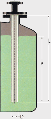
Dip Tubes and spargers used in agitated service are subject to loads which under certain conditions can be so great that bending or complete failure of the unit can occur. Therefore, it is important that these loads be considered when designing or specifying a dip tube or sparger for use in highly agitated service with highly viscous materials.
To determine these loads, the following must be known:
- V – Velocity of the process fluid past the tip of the dip tube (ft/sec)
- D – Outside diameter of the dip tube (ft) See table
- L – Entry Length of the dip tube (ft)
- φ – Length of the dip tube immersed in fluid (ft)
- µ – Dynamic viscosity of the process fluid (lbs sec/ft2)
- ρ – Mass density of the process fluid (slugs/ft3) [(1slug/ft3 =32.17lb/ft3)]
Note: These equations are provided as a guide only and do not constitute a warrarnty, expressed or implied, for the fitness of an Ethylarmor® Dip Tube in specific service
The total force exerted on the tube, F, can be determined from the above information. FT is the resultant of the drag and lift forces acting on the tube, FD and FL respectively. FT is given by Equation 1.
Equation 1
FT = vFD2 + FL2
The viscous drag force, FD, is defined by Equation 2.
Equation 2
- when: A = φ D
- FD = CD V2 ? A
2
the lift force FL, created by alternate vortex shedding on the back surface of the immersed tube is given by Equation 3.
Equation 3
FL = CL ρ V2 A
2
The coefficients for lift and drag, CD and CL, are based on the Reynolds number which can be calculated using Equation 4.
Equation 4
- Reynolds Number,
- R = ρ D V
µ
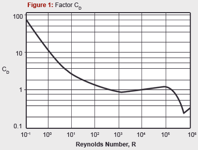
CD can be gotten from Figure 1 shown below.
- CL is as follows:
- CL = 0.8
- CL = 2.4 – 0.4Log10R
- CL = 0.4
- when:
- (R < 105)
- (105 < R < 106)
- (R > 106)
| Factors WD, H and D |
| |
Nominal
Size |
WD |
H |
D |
| 3/4 |
1,877 |
11.75 |
0.101 |
| 1 |
3,533 |
18.79 |
0.123 |
| 1-1/2 |
9,064 |
41.62 |
0.179 |
| 2 |
16,080 |
66.79 |
0.219 |
| 3 |
48,970 |
147.02 |
0.312 |
| 4 |
93.940 |
247.88 |
0.401 |
| 6 |
187,000 |
573.19 |
0.583 |
| 8 |
369,820 |
981.23 |
0.760 |
Equation 1 can be rewritten as:
Equation 5
FT = ρ V2 AvCD2 + CL2
2
The value obtained by Equation 5 must be less than or equal to the maximum allowable load recommended by Ethylene for the selected unit. The maximum load, Sm, for dip tube or sparger is given by Equation 6:
Equation 6
Sm =WD
12(L -0.5F)
where WD is the factor given in table
If FT < Sm, the unit is sufficiently strong for the intended service. However, a check for resonance should be made.
If the natural frequency of the dip tube is too close to the wake frequency, resonance can occur in the dip tube causing stresses much greater than expected. The natural and wake frequency must be calculated and the ratio of these frequencies must be greater than v2 or less than 0.5.
The natural frequency of the dip tube can be calculated using Equation 7 where the value of factor H is taken from table.
Equation 7
Wn = 135 vH/L4
The wake frequency, W, is calculated using Equation 8.
Equation 8
W = 0.22 V
D
The ratio W/Wn should be less than 0.5 or greater than v2
-
Example 1: Dip Tube is Adequate
| V, fluid velocity |
= 15 (ft/sec) |
| Dip tube size |
= 3” or 0.312 (ft) from the table |
| L, entry length |
= 80” or 6.67 (ft) |
| φ, immersed length |
= 65” or 5.52 (ft) |
| µ, dynamic viscosity |
= 1.10 centipoise or 2.298x10⁻⁵ 1lbs sec/ft2 |
| ρ, fluid mass density |
= 2.10 slugs/ft3 |
Step 1:
Determine Reynolds number,
R = (2.10• 0.312• 15)/2.298x10-5 =4.277x10⁵
Step 2:
Determine CD and CL
CD = 0.90(Fig.1), CL = 2.4 – 0.4Log10R (4.277x10⁵)=0.148
Step 3:
Calculate Force FT using Equation 5,
FT = 0.5• 2.10• 152• (.312• 5.42) x v0.92• 0.1482 = 364lbs
Step 4:
Calculate allowable force, Sm using Equation 6,
Sm = 48,970/(12•6.67-0.5•5.41)) = 1,030 lbs
Since 364 < 1,030 a 3” dip tube would be adequate for this application.
Step 5:
Determine the natural frequency, Wn, of the dip tube from Equation 7,
Wn = 135v147.024/6.674 = 36.8 Hz
Step 6:
Determine wake frequency, W, using Equation 8,
WD = 0.22• 15 / 0.312 = 10.6 Hz
Step 7:
Test ratio of W / Wn = 10.6 / 36.8 = 0.29
Since 0.29 < 0.5, the dip tube passes the test
-
Example 2: Dip Tube is Inadequate
| V, fluid velocity |
= 15 (ft/sec) |
| Dip tube size |
= 1-1/2 or 0.179 (ft) from table |
| L, entry length |
= 80” or 6.67 (ft) |
| φ, immersed length |
= 65” or 5.42 (ft) |
| µ, dynamic viscosity |
= 1.10 centipoise or 2.298x10⁻⁵ sec/ft2 |
| ρ, fluid mass density |
= 2.10 slugs/ft3 |
Step 1:
Determine Reynolds number,
R=(2.10• 0.179• 15)/2.298x10-5=2.454x105
Step 2:
Determine CD and CL
CD =0.90 (Fig.1), CL = 2.4-log10 (2.454x10⁵) = 0.244
Step 3:
Calculate force FT using Equation 5,
FT = 0.5• 2.10• 152• (.179• 5.42) x v0.92• 0.2442 = 214 lbs
Step 4:
Calculate allowable force, Sm using Equation 6,
Sm= 9064/(12•(6.67-0.5•5.41)) = 191 lbs
Since 214 < 191 a 1-1/2” dip tube would NOT be suitable for this application.
Step 5:
Determine the natural frequency, Wn, of the dip tube from Equation 7,
Wn = 135v41.62/6.674 = 24.8 Hz
Step 6:
Determine wake frequency, W, using Equation 8,
WD = 0.22• 15 / 0.179 = 15.1 Hz
Step 7:
Test ratio of W / Wn = 15.1 / 24.8 = 0.61
Since 0.5 < 0.61 < v2, the dip tube fails the test


